3D BIM Modeling for HVAC MEP Infrastructure Revit Coordination and Arch Viz Services

Complex HVAC and MEP systems fail on site when design teams cannot see how ducts, pipes, cables, shafts, ceilings, structure, and plant rooms compete for the same space. Flat drawings hide too much. A coordinated model makes the problem visible before labour and material reach site.
That is where BIM becomes practical. It is not only a 3D view. It is a data-rich method for planning, checking, documenting, and communicating building systems.

Why HVAC and MEP infrastructure needs BIM
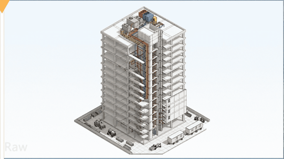
HVAC and MEP infrastructure is dense by nature. One ceiling zone can carry supply air ducts, return air ducts, chilled water lines, sprinkler pipes, electrical containment, lighting supports, access panels, and structural members. Each system has its own clearance, slope, insulation, access, and maintenance needs.
A 2D plan can show routing. It cannot show the full spatial conflict. Section drawings help, but they are often limited to selected slices. A coordinated BIM model shows the full system relationship across the building.
For HVAC and MEP, BIM helps teams check:
Duct and pipe routing through congested zones
Clearance above false ceilings
Plant room equipment access
Shaft sizes and riser coordination
Valve, damper, and filter access
Structural openings and sleeves
Service clashes before installation
Quantity take-offs and drawing production
Construction sequencing and maintenance planning
3D BIM Modeling also supports communication. Site teams, consultants, contractors, and clients can review the same spatial logic without reading every technical drawing in isolation.
What a correct HVAC and MEP BIM model contains in 3D BIM Modeling
A useful BIM model is built with purpose. It must carry geometry, data, and coordination logic. A model that only looks good may fail during construction. A technical model must be accurate enough to support real decisions.
HVAC model elements
HVAC BIM usually includes air-side and water-side systems. Common modelled elements include:
Air handling units
Fan coil units
Variable air volume boxes
Supply, return, exhaust, and fresh air ducts
Duct accessories such as dampers, silencers, and flexible connectors
Chilled water and condenser water pipes
Insulation thickness
Diffusers, grilles, and louvers
Equipment pads and maintenance zones
The duct size alone is not enough. Insulation, support clearance, access space, and fire separation can change the required space. A 600 mm duct may need more than 600 mm in the ceiling void once insulation and fixing systems are included.
Plumbing and fire protection systems
Plumbing and fire systems require slope, pressure, access, and code awareness. BIM models often include:
Domestic water lines
Soil and waste pipes
Rainwater pipes
Pump rooms
Tanks and filtration systems
Sprinkler mains and branches
Fire hose reels and hydrant systems
Drainage slopes and access points
Drainage pipes need particular care because gravity systems cannot simply be lifted or lowered without affecting slope. Early coordination protects headroom and reduces last-minute site changes.
Electrical and ELV systems
Electrical BIM includes more than cable trays. It also covers clearance around equipment, panel access, containment routing, and service segregation.
Typical elements include:
Cable trays and ladders
Conduits and trunking
Distribution boards and panels
Transformers and DG connections
Lighting layouts
Fire alarm and public address systems
CCTV and access control routes
Data and communication racks
Electrical containment often competes with ducts and pipes in corridors. Revit BIM coordination services help detect these conflicts in a combined model.
Revit coordination turns separate models into buildable information
Most large projects split design responsibility. Architects work on walls, ceilings, doors, finishes, and room data. Structural teams work on columns, beams, slabs, foundations, and openings. MEP teams work on HVAC, plumbing, fire, and electrical services.
Revit coordination brings these models together. The goal is not only to place models in one file. The goal is to create a coordinated environment where each discipline can be checked against the others.
A typical Revit coordination process includes:
Model setup
Teams define levels, grids, coordinates, units, naming rules, and linked model management. This avoids alignment errors later.
Discipline model creation
Architects, structural teams, and MEP teams build their discipline models using agreed standards.
Model federation
The separate models are linked or combined for review. Tools such as Revit and Navisworks are commonly used for coordination.
Clash detection
Hard clashes, soft clashes, and workflow clashes are identified. A hard clash may be a duct passing through a beam. A soft clash may be missing maintenance clearance around an AHU.
Issue tracking
Each issue gets assigned to a responsible team. It needs a location, screenshot, priority, and status.
Model revision
Teams revise routing, openings, levels, or equipment positions. The updated model is reviewed again.
Drawing and data output
Coordinated models produce plans, sections, schedules, shop drawings, and sometimes fabrication-level details.
A clash-free model is not automatically a buildable model. It must also respect access, sequence, support, tolerances, and maintenance.
Key coordination checks for HVAC and MEP
Good coordination is systematic. It does not rely on random visual review. The team must check the most failure-prone areas early.
Ceiling void coordination
Ceiling voids are the most common conflict zones. Corridors are especially tight because they carry long service runs. The model must account for:
Finished ceiling level
Duct depth and insulation
Pipe slope and insulation
Cable tray stacking
Fire stopping
Hanger depth
Light fixtures and access panels
Maintenance clearances
A ceiling zone may look clear until hanger rods, valves, dampers, and access panels are included.
Plant room coordination
Plant rooms need space for installation, operation, and replacement. BIM should show both equipment and access volumes.
Important checks include:
Equipment footprint
Door and removal paths
Valve access
Filter pull-out space
Pipe header clearance
Pump maintenance zone
Electrical panel clearance
Drainage routes
Mechanical BIM services are valuable here because plant rooms require both engineering logic and spatial discipline.
Structural openings and sleeves
MEP services often pass through beams, slabs, and walls. These openings must be coordinated with structure before construction. Late coring can weaken elements, delay work, and increase cost.
A structural BIM service provider helps validate openings against structural rules. Openings must be sized with tolerance, insulation, fire stopping, and sleeve requirements in mind.
Riser and shaft planning
Vertical services need early planning. Shafts must handle current routing and future access. BIM makes riser congestion visible across floors.
The team should verify:
Shaft clear width and depth
Fire separation
Pipe spacing
Valve access
Floor penetration positions
Coordination with toilets, ducts, and electrical risers
Maintenance access at each level
Levels of detail and model purpose
Not every BIM model needs the same level of detail. Over-modelling wastes time. Under-modelling creates site risk. The right level depends on the stage.
Project stage | BIM focus | Typical output |
Concept design | Space planning and major service zones | Indicative routes, plant space, shaft strategy |
Design development | System routing and coordination | Coordinated discipline models and key sections |
Construction documentation | Drawings and clash resolution | Coordinated plans, sections, schedules |
Shop drawing stage | Installation-level detail | Hangers, supports, sleeves, builder’s work |
As-built stage | Facility management record | Final installed routes and asset information |
BIM modelling services should match the project stage. A hospital, airport, data centre, metro station, or large commercial tower may need deeper coordination than a simple fit-out.
How BIM service providers support delivery
BIM service providers fill different roles depending on the project. Some act as modelling support. Some work as coordination leads. Some support construction documentation, fabrication drawings, or visual communication.
Common services include:
Revit BIM services for architectural, structural, and MEP modelling
BIM design services during design development
BIM drafting outsourcing for documentation-heavy projects
BIM design outsourcing for teams needing extra production capacity
BIM outsourcing services for remote model creation and drawing support
BIM modelling services for coordinated building systems
Architectural CAD and BIM services for plans, elevations, sections, and models
Mechanical BIM services for HVAC, plumbing, and fire coordination
Revit BIM coordination services for clash review and issue resolution
Many BIM companies and BIM consulting firms also provide model audits. This helps check naming, coordinates, levels, families, warnings, and documentation standards.
For international projects, teams often compare BIM in USA workflows with local delivery requirements. BIM companies in USA may follow client-specific standards, while Indian teams may support production, coordination, and documentation across time zones. Building information modeling companies and BIM modelling companies often work through structured exchange formats, model-sharing platforms, and issue trackers.
When searching for support, phrases like “bim services near me” can help with local vendors. For detailed remote delivery, compare bim outsourcing companies, a BIM modeling contractor, or the best BIM consulting services for detailed coordination based on sample work, model quality, communication method, and ability to understand construction intent.

BIM and Blender serve different roles
BIM and Blender are often mentioned together, but they solve different problems. BIM tools such as Revit manage building elements, parameters, schedules, views, and construction documentation. Blender is a 3D creation tool used for modelling, rendering, animation, and visual storytelling.
A BIM Blender workflow can be useful when the goal is visualisation. A technical Revit model can be exported and cleaned for rendering, animation, AR, VR, or project trailers. This does not replace BIM coordination. It turns coordinated information into clearer visual communication.
Many people search for Blender through terms such as Game Blender Engine, game blender engine, blender game dev, blender video game, mobile blender, android blender apk, blender on android, iPhone Blender, Blender on MacBook, Blender laptop, blender web version, play blender, picture blender app, 2D animation Blender, how to get Blender, Blender 3D model download, gamefile blender free, file Blender free, and does Blender cost money. These searches point to a broad interest in Blender as a creative tool.
For AEC work, the relevant point is simple. Blender can help produce renders, animations, and walkthroughs. BIM remains the technical base for coordinated building information.
What makes a BIM model reliable
A reliable BIM model has discipline behind it. Good geometry is only one part of quality.
Check these points before using a model for construction decisions:
Shared coordinates
Linked models must align correctly. Wrong coordinates can create false clashes or hide real ones.
Consistent levels and grids
Floor levels, reference levels, and grids must match across disciplines.
Correct family categories
Elements must be placed in the right categories so schedules and filters work.
Accurate dimensions
Ducts, pipes, insulation, cable trays, and equipment must match design intent.
Modelled access space
Maintenance zones should be visible, especially around valves, filters, panels, and plant equipment.
Updated issue status
Clash reports must not remain static. Open, resolved, approved, and rejected issues need clear tracking.
Clean drawing output
Plans, sections, and schedules must come from the coordinated model where possible.
From technical models to architectural visualisation
BIM helps teams build correctly. Architectural visualisation helps teams understand and present the project clearly. The two work best together.
A coordinated BIM model can support:
3D walkthrough videos for client and stakeholder review
3D BIM animations for explaining systems and construction sequence
AR and VR walkthrough videos for immersive spatial review
Engineering animation videos for process, MEP, and equipment explanation
Project trailers and promos for launch, marketing, and approvals
Still renders for presentations, reports, and public communication
This is useful for complex HVAC and MEP work. A plant room animation can show how air, water, and power systems connect. A hospital corridor walkthrough can explain ceiling service coordination. A VR model can help decision-makers understand access, ceiling height, and equipment placement before fit-out begins.
How to choose the right BIM and Arch Viz partner
Choose a team that can read drawings, understand construction, and create clear visuals. A beautiful animation is not enough if the technical base is wrong. A technically correct model is not enough if stakeholders cannot understand it.
Look for:
Experience with architectural, structural, HVAC, plumbing, fire, and electrical models
Ability to work with Revit, Navisworks, CAD, and visualisation workflows
Clear model exchange and review process
Clash detection and issue reporting discipline
Understanding of LOD and project stage requirements
Strong visual storytelling for walkthroughs and animations
Capacity to support both design and presentation needs
Film by Him provides a one-stop solution for architectural visualisation services, including 3D walkthrough videos, 3D BIM modelling, 3D BIM animations, AR and VR walkthrough videos, engineering animation videos, project trailers, and promos. If the project needs technical clarity and strong visual presentation, connect with the Film by Him Arch Viz team.
The takeaway
HVAC and MEP coordination is too complex for isolated drawings alone. BIM gives teams a shared, spatial, data-rich way to plan services, detect clashes, protect access, and reduce site confusion.
Revit coordination builds the technical base. Architectural visualisation turns that base into clear communication. When both work together, complex infrastructure becomes easier to review, explain, approve, and build.
Your Next Big Dream Project Deserves Better Than Average ArchViz. Let’s Connect and Make It Unforgettable.

Comments