
4D BIM Revolution Transforming Architectural Design

A flat drawing can show walls, doors, grids, and levels. It cannot show the sequence of a site coming alive.
That gap has shaped architecture for decades. Designers drew. Engineers checked. Contractors interpreted. Site teams built from stacks of plans, sections, and schedules. The system worked, but it created blind spots.
Now the model can show the building, the data behind it, and the way it will rise over time. That is why 4D BIM is changing architectural design from a drawing-led process into a visual planning process.

Why 2D drawings shaped architectural work for so long
For years, 2D drawings were the main language of architecture.
A floor plan showed the layout. An elevation showed the face of the building. A section cut through the structure and explained height, depth, and levels. Details showed joints, materials, and construction methods.
This worked because it was precise. A skilled architect could explain a complete building through drawings. A skilled contractor could read those drawings and understand what had to be built.
But the process had limits.
A building is not flat. It has depth, services, structure, access routes, construction stages, material lead times, and site constraints. A full project might require hundreds or even thousands of sheets. Each sheet shows one part of the story.
That creates room for error.
A duct may pass through a beam. A door may clash with furniture. A ceiling height may look fine in plan but fail when services run above it. A staircase may meet code in one drawing but create headroom issues in another. These problems often appear late, when fixes cost more.
2D CAD improved drafting speed. It made changes cleaner. It reduced manual redrawing. It also helped teams store, print, and share drawings with greater control.
But CAD did not fully change the thinking. It still used lines to represent objects. A wall was often a set of lines. A door was a symbol. A beam was a shape. The intelligence lived in the mind of the designer and in separate schedules.
That is the weakness BIM began to solve.
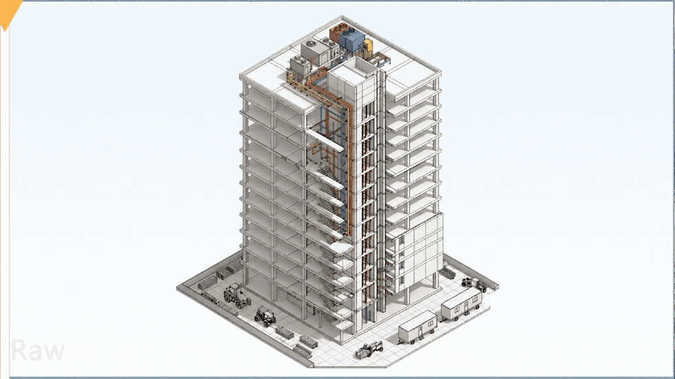
What 4D BIM and BIM changed in architectural design
BIM changed the object behind the drawing.
In a conventional CAD file, a line is a line. In a BIM model, a wall is a wall. It can contain height, thickness, material, fire rating, finish, and cost-related data. A door can carry size, swing, hardware, acoustic rating, and manufacturer details. A slab can know its level, build-up, and relationship to other elements.
This matters because the model becomes a shared source of information.
When a wall moves, the plan changes. The section changes. The 3D view changes. Schedules can update too, if the model has been set up properly. This reduces repeated work and helps teams catch inconsistencies earlier.
BIM also makes design easier to understand.
Many clients, site supervisors, and even project stakeholders struggle to read complex drawings. A 3D model closes that gap. It shows volume, scale, and spatial relationships. It helps people see what a space will feel like before work begins.
For architects, this changes the design process in practical ways:
Better coordination
Structural, architectural, and MEP models can be checked together.
Earlier clash detection
Conflicts can appear before they reach site.
Clearer design reviews
Teams can inspect a model rather than compare many sheets.
More reliable quantities
Model-based schedules can support faster estimation.
Improved communication
A visual model reduces confusion across teams.
BIM does not remove the need for drawings. Construction still needs clear plans, sections, and details. But those outputs can now come from a coordinated model rather than separate manual drafting streams.
The fourth dimension adds time to the model
The next step is simple to understand and powerful in use. Add time.
A 3D BIM model shows what the building will be. A time-linked model shows when each part will be built. It connects model elements to construction activities, such as excavation, foundation work, column casting, slab cycles, blockwork, façade installation, MEP rough-ins, and finishing.
This turns the construction programme into a visual sequence.
Instead of reading a bar chart and imagining the site, teams can watch the building develop stage by stage. Basement work appears first. Then columns. Then slabs. Then services, façade, and interiors. The model becomes a moving construction plan.
This is useful because construction is not only about the final design. It is also about order.
A good design can fail on site if the sequence is poor. Materials may arrive too early. Temporary works may block access. Two trades may need the same zone at the same time. A crane may not reach a planned location. A façade panel may need installation before an internal wall closes access.
A time-based model brings these issues into view.
It also helps non-technical stakeholders. A project owner may not read a detailed schedule. A local authority may not study every construction drawing. A resident welfare association may not understand phasing from a spreadsheet. A visual sequence is easier to explain.

How design thinking changes when time is visible
The move from 2D CAD to BIM is not only a software change. It changes how teams think.
In 2D drafting, the main question is often, “Is the drawing correct?”
In BIM, the question becomes, “Does the building work as a system?”
In time-based BIM, the question expands again: “Can this building be built in this sequence, within the planned time, with fewer conflicts?”
That shift affects decisions early in the project.
Architects can test buildability sooner
Some design choices look fine in a 3D view but create site problems. A complex façade may need special access. A large cantilever may require longer temporary support. A narrow service shaft may slow installation and maintenance.
When the model links to time, these choices become easier to review. The team can see which design elements affect the programme. They can test alternate sequences before drawings go to site.
Engineers can coordinate with more context
Structural and MEP teams often work under tight constraints. They need enough space for beams, ducts, pipes, cable trays, fire systems, and maintenance access.
A time-linked model helps them see not only where services go, but also when they must be installed. This improves planning in congested areas such as basements, plant rooms, hospital service zones, airports, data centres, and metro station works.
Contractors can plan work zones clearly
On a live site, space is limited. Storage, access, labour movement, safety zones, scaffolding, and equipment all compete for room.
A visual sequence helps contractors divide the site into workable zones. It can show when a floor becomes available, when a trade should enter, and when a zone must stay clear.
This does not replace site judgement. It supports it.
The difference between 2D CAD, 3D BIM, and time-based BIM
The evolution becomes clearer when compared side by side.
Method | What it shows | Main strength | Main limit |
2D CAD | Plans, elevations, sections, and details | Precise technical documentation | Requires interpretation across many drawings |
3D BIM | A coordinated digital building model with data | Better visualisation and clash detection | Does not always show construction sequence |
Time-based BIM | A model linked to the project schedule | Shows how the building develops over time | Needs accurate model data and schedule discipline |
Each stage has value. The strongest teams do not treat them as enemies. They use the right output for the right task.
2D drawings still matter for approvals, tendering, and execution. 3D BIM helps with coordination and decision-making. Time-linked models help connect design intent with site planning.
Why this matters on Indian construction projects
Indian projects often face tight timelines, dense sites, mixed trade coordination, and fast design changes. Residential towers, commercial complexes, hospitals, industrial buildings, airports, and infrastructure projects all involve many teams working at once.
In this context, visual planning has real value.
A time-linked model can help show:
When excavation and retaining work affect site access
How tower cranes and material hoists support each phase
Which floors are ready for MEP work
When façade installation can start
Where interior trades may clash
How temporary routes must change as work progresses
Which delayed activity may affect later stages
This supports better conversations between architects, consultants, contractors, and owners.
It also helps during progress review. The planned sequence can be compared with actual site status. If the structure is delayed, teams can see which downstream tasks will move. If one zone advances faster, labour and material plans can adjust.
The value lies in clarity. When more people can see the same plan, fewer decisions depend on guesswork.
What teams need before moving beyond drawings
Software alone does not create good BIM. A weak model linked to a weak schedule will not produce reliable results.
Teams need sound basics first.
Clear modelling standards
Every model needs rules. Elements must be named properly. Levels must be consistent. Categories must be used correctly. Model detail should match the project stage.
A concept model does not need every bolt. A construction model needs much more accuracy. Too little detail creates gaps. Too much detail too early slows the team.
Reliable project schedules
A time-based model depends on the construction programme. If the schedule is vague, the simulation will be vague.
Activities should match real work packages. They should reflect site logic. The sequence should make sense to the people who will build the project.
Shared responsibility
BIM is not only the architect’s job. Structural engineers, MEP consultants, contractors, planners, and quantity surveyors all add value.
The model works best when each team shares accurate information. Poor inputs create poor outputs.
Regular updates
A model created once and ignored becomes outdated fast. Design changes, site delays, procurement issues, and revised methods all affect the plan.
The model and schedule should be reviewed at key project stages. On large projects, this review may happen often. On smaller projects, it can happen at major milestones.
The risks of treating BIM as a visual trick
A polished animation can impress people. That does not mean it is useful.
A time-based simulation must be tied to real project data. If it only shows a nice sequence, it becomes a marketing visual. If it reflects actual planning logic, it becomes a project tool.
Common mistakes include:
Linking model parts to broad schedule items with no detail
Ignoring temporary works and access constraints
Using outdated models for planning reviews
Modelling too much detail that does not support decisions
Treating the animation as final truth instead of a planning aid
Leaving site teams out of the review process
Good BIM is practical. It should answer clear questions.
Can this work happen in this order? Will two trades clash? Can the site handle the material flow? Is the planned sequence safe? Does the model match the current design? What happens if a major activity slips?
If the model helps answer those questions, it has value.
The future of architectural drafting is visual and connected
Architectural drafting will not disappear. Buildings still need drawings. They still need details, dimensions, notes, and approvals.
But drafting is no longer the whole story.
The future points towards connected models that carry geometry, data, cost links, and time. Architects will still design spaces. Engineers will still solve technical problems. Contractors will still build on site. The difference is that more decisions can happen with a clearer view of the building before physical work begins.
This changes the role of documentation.
Drawings become one output from a richer model. Schedules connect to visual sequences. Reviews become easier to understand. Site teams can plan with better context. Owners can see progress in a form that matches reality.
The result is not perfect construction. No tool can remove weather delays, labour issues, late approvals, or supply problems. But better visual planning reduces avoidable confusion. It helps teams spot risks sooner. It creates a stronger link between design intent and execution.
For project teams that need strong visual communication, cinematic walkthroughs, construction sequences, and built-environment storytelling can add another layer of clarity. Explore more visual work at Film By Him.
The shift from flat drawings to time-linked models is a clear step forward. Architecture is moving from showing what a building looks like to showing how it will come together. That is a better way to design, plan, and build.
Your Next Big Dream Project Deserves Better Than Average ArchViz. Let’s Connect and Make It Unforgettable.


Comments